
Infrared Specifications for Aviation Obstruction Light Compatibility with Night Vision Goggles (NVGs)
FAA Airports
Infrared Specifications for Aviation Obstruction Light Compatibility with Night Vision Goggles (NVGs)
1. Purpose.
This Engineering Brief (EB) 98 provides information about the interaction of Light Emitting Diodes (LEDs) used in obstruction lighting fixtures with Night Vision Imaging Systems (NVIS) on board both rotary and fixed-wing aircraft. In addition, this engineering brief provides performance specifications for infrared (IR) emitters to be added to or used in conjunction with LED L-810, L-864 and L-885 obstruction light fixtures to ensure compatibility with Night Vision Goggles (NVGs) with a Class B filter. These changes are necessary in order to address the concern that certain LED obstruction lighting systems fall outside the combined visible and near-infrared spectrum of NVGs with a Class B filter.
2. Background.
The use of NVGs is increasing in civilian aviation to conduct search-and-rescue, emergency medical transport, and other flight operations. The use of NVIS can function to increase pilot situational awareness. However, the Federal Aviation Administration (FAA) has found that with the gradual replacement of incandescent obstruction light fixtures with LED light fixtures, some pilots using NVGs are unable to acquire red-colored LED obstruction lights due to the light generated being outside of the combined visible and near-infrared spectrum of NVGs with objective lens filters. NVIS definition: A night vision imaging system is an optical instrument that allows images to be produced in levels of light approaching total darkness. NVGs constitute one component of a NVIS. NVGs in aviation are designed to be used for flying at night, primarily during Visual Meteorological Conditions (VMC). They are mounted in a binocular form on a pilot’s helmet. The term usually refers to a complete unit, including an image intensifier tube, a protective water-resistant housing, and mounting system. The potential problem: Pilots using NVIS equipment that filter the adverse effects of cockpit lighting might not be able to see LED-based obstruction lighting. The preceding could result in a safety hazard to both the pilot and ground personnel. NVGs function by amplifying ambient light, allowing the pilot to better see terrain and other potential hazards in dark or overcast conditions. NVGs help pilots maintain spatial orientation and general situational awareness.
LED-based lighting has largely replaced incandescent technology for red (and some white) obstruction lighting because of its reduced maintenance requirements and extended service life. Traditionally, NVIS systems were built to detect the high short wave IR emission of incandescent-based lights – this facilitated easy detection despite the presence of filters for the aircraft cockpit/avionics lighting. This is no longer true with LEDs which have little IR emission. In addition, LEDs have a relatively narrow band of spectral emission. The same cockpit lighting filters used to block red emission from the cockpit lighting may prevent the pilot from seeing LED obstruction and aviation ground lighting.
3. Application.
The Federal Aviation Administration (FAA) requires that the guidance in this EB be used with the other applicable documents listed in Section 6.
4. Description.
This EB describes the interaction of LEDs used in obstruction lighting fixtures with NVIS and provides specifications to facilitate the addition of IR emitters to L-810, L-864 and L-885 LED-based obstruction lights in order to ensure compatibility with NVIS.
5. Current Obstruction Lighting Standards and NVG Spectrum Requirements
The FAA currently has in place standards and recommended practices for the marking and lighting of obstructions. Generally, obstructions include structures with heights of 200 ft. above ground level (AGL) or greater, and structures on, or in the vicinity of airports.
6. L-810, L-864 and L-885 Obstruction Lighting Fixtures
Aviation red obstruction lights are used to increase conspicuity of obstructions during nighttime. The red obstruction light system is composed of flashing omnidirectional lights (L-864 and L-885) and/or steadyburning or flashing (L-810) lights. Recommendations on lighting structures can vary, depending on terrain features, weather patterns, geographic location, and number of structures. Specific guidance and installation criteria for obstruction lighting equipment are found in AC 70/7460-1, Obstruction Marking and Lighting. AC 70/7460-1 recommends obstruction avoidance safety margins: “A pilot in an aircraft flying at a speed of 165 kt (190 mph/306 kph) or less should be able to see obstruction lights in sufficient time to avoid the structure by at least 2,000 feet (610 m) horizontally under all conditions of operation, provided the pilot is operating in accordance with 14 CFR Part 91. Pilots operating 250 kt (288 mph/463 kph) aircraft should be able to see the obstruction lights unless the weather deteriorates to 1 statute mile (1.6 km) visibility at night, during which time period 2,000 candelas enables the light to be seen at 1.2 statute miles (SM) (1.9 km)”. AC 70/7460-1 notes that the 2,000-foot avoidance distance was intended to protect aircraft from collision with guy wires utilized on 2,000-foot structures: “The guy wires at a 45-degree angle would be at a distance of 1,500 feet from the structure at a 500-foot elevation. Since the aircraft is to be 500 feet clear of obstacles (the guy wire), the distance of avoidance from the structure is 1,500 + 500 = 2,000 feet.”
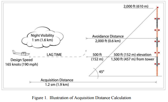
The acquisition and avoidance distances of pilots using NVG with LED based obstruction lights with an IR emitter should meet or exceed the nighttime acquisition distances of pilots without the aid of NVG. A L-810 fixture with an IR emitter should be acquired at a minimum distance of 1.4 SM and a L-864/L-885 fixture should be acquired at a minimum distance of 3.1 SM.
7.NVG Operation
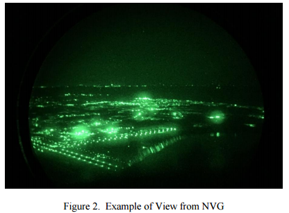
The use of NVGs enables a pilot to improve his/her situational awareness during nighttime VMC. NVGs function by amplifying ambient light through a process of image intensification. Using NVGs in dark conditions, pilots can see the terrain and perform flight operations.
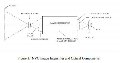
NVGs consist of three main components: the eyepiece lenses, the objective lenses, and the image intensifier tubes, as shown in figure 3. The design and configuration of these components determine the overall performance of the NVGs. The image intensifier tubes generally are the most critical component determining image clarity, though the eyepiece and objective lenses can also affect performance.
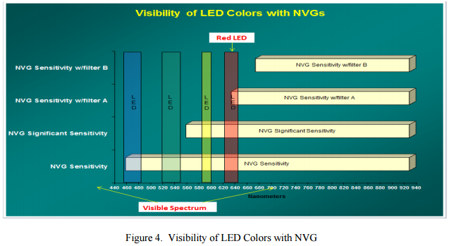
Current NVGs are sensitive to light with wavelengths between approximately 450 nanometers (nm) and 920 nm. This range overlaps the visible spectrum of light (approximately 390 nm to 700 nm). If the visible light in the cockpit is not effectively filtered by the NVGs, the automatic gain control of the NVGs will be activated and will potentially reduce the visual acuity of the pilot. As a result, filters are installed on the objective lenses of the NVGs. NVG filters currently in use include Class A, Class B, and Class C. Class A filters restrict wavelengths below 625 nm from being viewed by the NVG, allowing the use of blue, green, and yellow lighting to be used in the cockpit. Class B filters restrict lighting with wavelengths below 665 nm from being viewed by NVG, allowing the use of some red lighting in cockpit displays. Class C filters, also known as “leaky green” filters, also restrict light wavelengths below 665 nm, with the exception of a limited amount of green for a heads up display.
Class A NVG filters can view colors with wavelengths 625 nm and above, and Class B filters can view colors with wavelengths of 665 nm and above. However, because red LED obstruction lights have a limited emission range (approximately 620 nm to 645 nm) as shown in Figure 4, some red LEDs may have limited visibility using Class A filters and no visibility using Class B filters.
8.Proposed Infrared Specifications for LED Obstruction Lights
In order to be NVG compatible, LED-based L-810, L-864 and L-885 obstruction light fixtures must include IR emitters or be used in conjunction with a standalone IR emitter. The IR emitters are to be on whenever the visible light is energized and off whenever the visible light is de-energized. IR specifications are stated below to resolve the issues precluding the acquisition of LED obstruction light fixtures by pilots using NVGs with a Class B filter.
9. Output Wavelength
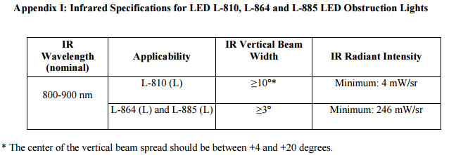
The nominal IR output wavelength is 800-900 nm. This range coincides with the nominal spectral response range of NVGs, ensuring the fixtures will be visible by all current NVGs regardless of the class of objective lens filter used.
10. Beam Width
For LED-based L-810, L-864 and L-885 light fixtures, the vertical radiometric requirements of the IR radiation are to be identical to the existing FAA requirements in AC 150/5345-43 for the photometric beam width and distribution of the visible light. Therefore, the vertical beam width of IR emitters included in a LED-based L-810 light fixture or used in conjunction with a LED-based L-810 light fixture is minimum 10°, centered between +4 and +20°. The vertical beam width of IR emitters included in a LED-based L-864 and L-885 fixture or used in conjunction with a LED-based L-864 and L-885 light fixture is minimum 3°. The horizontal beam width is 360° unobstructed. The IR emissions must mimic
both pulse width/duration of visible light so pilots do not experience a visual disparity when looking through and under the NVG.
11.Minimum IR Radiant Intensity
For wavelengths from 800 to 900 nm, the minimum radiant intensity for IR emitters included in LEDbased L-810 light fixtures or for standalone IR emitters to be used in conjunction with LED-based L-810 light fixtures is 4 milliwatts per steradian (mW/sr) [0.004 W/sr]. The minimum radiant intensity for IR emitters included in LED-based L-864 and L-885 light fixtures or for standalone IR emitters to be used in conjunction with LED-based L-864 and L-885 light fixtures is 246 milliwatts per steradian (mW/sr) [0.246 W/sr]. The minimum IR radiant intensities for LED-based L-810, L-864 and L-885 light fixtures are based on the minimum acquisition distances for nighttime VMC stated in AC 70/7460-1 (1.4 SM for the L-810 and 3.1 SM for the L-864/L-885). These distances are necessary to provide pilots with adequate time to see the obstruction and take evasive action to avoid coming within 2,000 ft. of an obstruction.
Note: In the event of a failure of the IR emitter, the visible light must be de-energized and an alarm signal must be generated to provide indication of the failure. The IR emitter must be monitored in accordance with the monitoring requirements for FLASH/FAIL status of L-864, L-810 and L-885 visible light units in AC 150/5345-43.
Anhang Technology(HK) Company Limited
all rights reserved © ICP:12060043
